Material burning is a warning, not a normal sign of powerful CNC cutting. When a router leaves brown edges, black dust, or a sharp burnt smell, heat is staying inside the cut instead of leaving through chips. This raises an important troubleshooting question: why is my CNC machine burning the material during cutting? The answer usually involves incorrect spindle speed, feed rate, tool geometry, tool wear, poor chip evacuation, or insufficient cooling. Sometimes, several small errors combine.
The U.S. Department of Energy’s 2022 Industrial Decarbonization Roadmap identifies process efficiency and energy reduction as major manufacturing priorities. Excessive cutting heat directly reflects inefficient energy use. OSHA’s Combustible Dust National Emphasis Program also highlights the fire risks created by fine dust from machining operations. These findings support a practical rule: burning material requires both quality control and safety attention. Stop the cut. Check the workpiece.
For wood, plastics, aluminum, and composites, the correct settings differ sharply. A dull two-flute cutter may rub instead of cut. A slow feed can leave the tool spinning against one narrow groove. Dust packed around the cutter can then trap heat like insulation. The cut tells you. Inspect the flute edges, collet grip, spindle runout, toolpath direction, and extraction airflow. Review the manufacturer’s cutting-data sheet before changing parameters. A perfect diagnosis is rarely available from one symptom. Blaming the CNC machine immediately is a weak assumption. Reliable Chinese CNC manufacturers should provide test-cut records, recommended feeds and speeds, thermal protection details, and documented quality procedures, ideally aligned with recognized ISO practices.
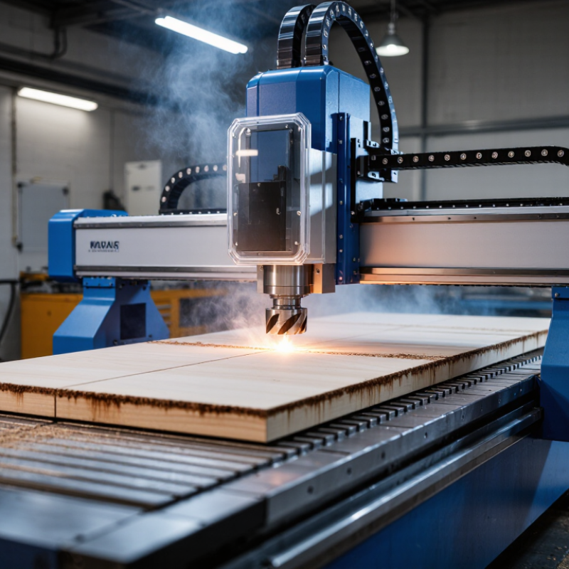
Material burning usually begins with excessive heat, not flame. A dull cutter rubs instead of cutting, creating dark edges, melted plastic, or scorched wood. The ASM Handbook, Volume 16, explains that cutting energy becomes heat at the tool–workpiece interface. Most heat leaves with the chip, but poor chip removal forces heat back into the surface. It happens quickly.
Cutting speed is a common trigger. NIST lists aluminum’s melting point at 660.3°C, while many plastics soften far below that temperature. Therefore, a plastic part may melt even when the tool looks clean.
Feed rate also matters. An extremely low feed can make each flute polish the material, increasing friction. Too many flutes can worsen this problem by restricting chip space. A practical check is simple: inspect the chips. Powder suggests rubbing; long, hot chips suggest poor evacuation.
Tool geometry and cooling deserve equal attention. A sharp, material-specific cutter, suitable rake angle, and open flute design reduce heat generation. Air blast can clear chips, but it may not cool deep pockets effectively. ISO 3685 uses flank wear as a tool-life indicator, yet visible wear is often noticed too late.
Shops sometimes increase coolant first. That is not always correct. Wrong coolant concentration, excessive spindle speed, or an unstable workholding setup can still cause burning.
Trial cuts should record spindle speed, feed rate, chip shape, and edge temperature. The process may need adjustment, not another tool.
Excessive speed increases friction at the cutting edge and raises heat around the workpiece. Dark edges, smoke, or a burnt smell are warning signs. Stop and inspect.
Yes. A low feed may make the tool rub instead of cut, especially during shallow passes. The surface can become hot and polished. It looks smooth, but it may be damaged.
A high feed can overload the tool, bend thin material, or leave rough marks. Check feed per tooth, not only total machine feed. Settings can change with another cutter.
Chips trapped inside a narrow slot can carry heat back into the cut. Long, blue chips suggest excessive heat. Powdery chips may indicate rubbing or a damaged edge.
A dull edge often rubs instead of cutting, leaving dark marks and a sharp smell. Incorrect geometry can also trap chips. Sharpness matters more than tool material alone.
Wood may scorch when dust blocks the flute or extraction path. Plastic can soften at high speed. Aluminum may stick to the cutting edge and create sudden friction.
Flood coolant can control heat during metal cutting. Air cooling often suits wood and some plastics. Weak flow, poor concentration, or clogged nozzles reduce protection.
Continuous marks often suggest rubbing or insufficient cooling. Isolated spots may indicate chip recutting or sudden tool loading. Check the tool, chips, sound, and spindle-load changes together.
No. Lowering speed may help, but a lower feed can increase rubbing. Make a small test cut on scrap material. My first adjustment is not always correct.
Material burning during CNC machining usually results from excessive heat at the cutting zone. If cutting speed is too high, feed rate is too low, or the tool is dull, friction increases and heat cannot escape efficiently. Hard or heat-sensitive materials, incorrect tool geometry, insufficient coolant, and poor chip evacuation can further raise the risk. Understanding why is my CNC machine burning the material during cutting requires checking the relationship between tool condition, machining parameters, material properties, and cooling performance.
Burn marks may appear as dark discoloration, melted edges, rough surfaces, or changes in material hardness. To diagnose the problem, inspect the tool for wear, review cutting data, examine chip shape, and verify coolant flow and concentration. Prevention involves balancing spindle speed with feed rate, selecting a suitable sharp tool, reducing excessive engagement, improving chip removal, and applying coolant correctly. Regular machine cleaning, tool replacement, alignment checks, and maintenance also help control heat and maintain consistent surface quality.

 DentFix Tool