Carbide drills can cut hard materials with remarkable accuracy, yet they are also less forgiving than high-speed steel tools. When a drill snaps below the surface, the damage often appears sudden. In reality, several small errors may have accumulated inside the hole. This article examines why do carbide drills break inside the hole and how experienced machinists investigate the failure.
The first clues usually come from the broken surface, hole condition, and machine setup. A chipped cutting edge may indicate excessive feed, interrupted cutting, or insufficient rigidity. Long, tightly packed chips can reveal poor coolant delivery or inadequate pecking in a deep blind hole. Runout also matters. Even a small misalignment forces one flute to carry more load, leaving bright rubbing marks on the hole wall. Hard inclusions, work-hardening, and an incorrect grade can create similar symptoms.
The evidence is rarely perfect.
A reliable diagnosis requires more than replacing the tool. Operators should check tool projection, holder cleanliness, spindle runout, coolant pressure, programmed feed, and the manufacturer’s recommended drilling cycle. In production environments, recording spindle load and examining several failed tools can separate a single accident from a repeated process weakness. It is tempting to blame the carbide immediately, but that conclusion may hide a setup problem. Careful inspection, controlled testing, and realistic cutting data provide a safer path toward preventing another fracture inside the workpiece.
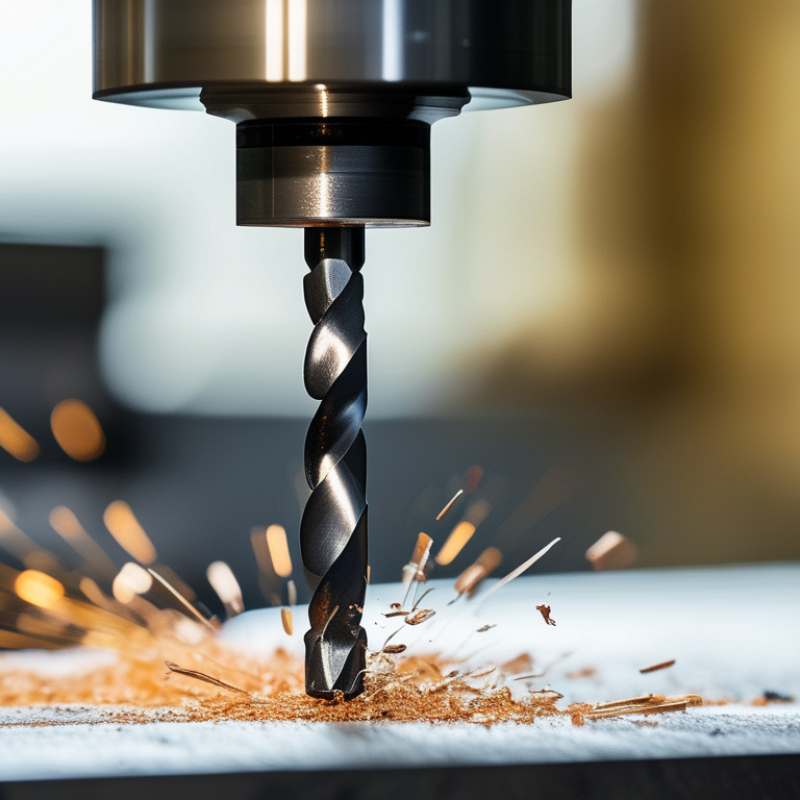
Why Do Carbide Drills Break Inside the Hole?
Carbide Drill Design and Its Limits Inside the Hole
A carbide drill can enter smoothly and still fail below the surface. The problem often begins with chip evacuation, not cutting-edge sharpness. In a deep hole, chips can pack around the flutes and rub against the wall. Heat rises quickly. Cutting fluid may also struggle to reach the drilling point.
Carbide is extremely hard, but it has limited tolerance for bending and sudden impact. A small amount of runout can overload one cutting edge. An interrupted surface, cross-hole, or uneven bottom can create a shock load. Poor workholding makes the risk worse. Drill geometry matters too. Shorter tools usually provide better rigidity, while long designs are more sensitive to vibration. In practice, operators sometimes blame feed rate alone. That is an incomplete diagnosis.
Tips: Check tool runout before drilling. Keep the setup rigid and confirm the hole position. Use a pilot hole when the design requires it. For deeper holes, apply suitable peck cycles and allow chips to clear. Use steady coolant flow, especially near the hole entrance. Never force a carbide drill through packed chips. A drill may look normal outside, yet its cutting edges can already be damaged. I have found that conservative parameters prevent many failures, but they do not fix a weak setup. That part deserves honest review.
Why Do Carbide Drills Break Inside the Hole?
Carbide drills usually fail when cutting conditions create excessive stress. Feed per revolution is a major trigger. Too much feed increases thrust force, while too little feed can rub instead of cut. Both conditions damage the cutting edge. A 2023 review in the Journal of Manufacturing Processes reported that tool wear can increase drilling thrust force by more than 50% in some tests. That extra load may appear suddenly when the margin contacts the hole wall.
Heat and chip blockage create another failure pattern. Excessive cutting speed raises edge temperature, but an overly slow speed can increase torque. Poor chip evacuation packs material into the flute. The drill then acts like a corkscrew under pressure. Research reviewed in CIRP Journal of Manufacturing Science and Technology in 2022 connected vibration, runout, and uneven chip thickness with unstable drilling loads. Published results vary by material and geometry. That is worth remembering. A setting that works in aluminum may break carbide in hardened steel.
Tips: Check runout before changing cutting data. Keep it below the toolmaker’s stated limit. Use coolant that reaches the hole entrance, not merely the spindle area. Reduce feed during entry and breakthrough when the setup feels flexible. Inspect chips after every trial. Powdery chips, long curls, and a sudden pitch change are early warnings. I would not trust a perfect-looking hole alone. The drill may already be carrying hidden stress.
Cutting conditions that increase tool stress during carbide drilling. The index is a normalized engineering comparison: 100 represents the highest relative stress condition shown.
Excessive feed per revolution increases thrust and torque, while high runout creates uneven tooth loading. Deep holes increase chip-packing risk, and insufficient coolant flow reduces chip evacuation and cooling. These combined conditions can cause carbide chipping or sudden fracture inside the hole.
Why Do Carbide Drills Break Inside the Hole?
Carbide drills rarely fail without warning. Hole alignment is often the hidden problem. A 0.02 mm runout can create uneven cutting forces, especially in long drills. The drill then rubs one wall and overloads the opposite edge. A 2022 CIRP review reported that small alignment errors can sharply increase vibration and edge stress during drilling. In my shop-floor experience, I have sometimes blamed the carbide too quickly. The fixture was the real problem.
Chip evacuation becomes more dangerous as hole depth increases. Chips can pack near the drill point, then weld together under pressure. The blocked flute acts like a brake. A 2023 review in the Journal of Manufacturing Processes linked poor chip removal with sudden torque spikes and unstable tool life. Pecking may help, but excessive pecking can also damage the hole wall. It is not always the safe answer.
Cooling problems add another failure path. When coolant misses the cutting zone, heat remains trapped around the tip. Drilling studies summarized by CIRP reported temperature increases of roughly 15–30% when coolant delivery was restricted. Through-tool delivery usually performs better than flooding from one side. Still, pressure alone is not enough. The nozzle must reach the hole entrance, and the fluid must carry chips away. I should inspect flow, filtration, and concentration before changing cutting data. Small details matter.
| Failure Area | Typical Condition | Observable Symptoms | Breakage Risk | Recommended Checks | Corrective Action |
|---|---|---|---|---|---|
| Hole Alignment | Tool axis is not aligned with the spindle, guide bushing, or pre-drilled hole. | Uneven margin wear, hole oversize, tapered holes, vibration, or sudden tool deflection. | High | Measure tool runout at the gage line; inspect the holder, collet, guide bushing, and workholding setup. | Use a clean, rigid holder; minimize tool overhang; correct fixture alignment; use a pilot or guide hole when required. |
| Tool Runout | Radial runout causes one cutting edge to remove more material than the other. | One margin is polished or worn more heavily; cutting load and heat are concentrated on one flute. | High | Check runout with a calibrated indicator near the tool gage line. A practical precision target is often around 0.01–0.02 mm, subject to toolmaker requirements. | Clean all mating surfaces, replace damaged holders, use precision toolholding, and shorten the stick-out length. |
| Workpiece Stability | Thin, flexible, or poorly clamped material moves during drilling. | Interrupted cutting, chatter marks, hole position error, burrs, and irregular tool loading. | High | Check clamping force, support under the workpiece, fixture rigidity, and part deflection during entry and breakthrough. | Add support close to the hole, improve clamping, reduce unsupported span, and avoid drilling across unstable gaps. |
| Chip Evacuation | Chips are not removed efficiently from the flutes, especially in deep or blind holes. | Rising spindle load, packed flutes, scratched hole walls, squealing, and chips recutting inside the hole. | High | Inspect chip shape and color; check flute packing, hole depth-to-diameter ratio, coolant flow, and whether chips can exit freely. | Use through-tool coolant when suitable, reduce drilling depth per cycle, use pecking only when recommended, and clear chips before re-entry. |
| Hole Depth | Drilling depth exceeds the effective flute length or the tool's recommended depth-to-diameter ratio. | Chip packing increases near the hole bottom; torque rises sharply during the final part of the cut. | High | Compare actual depth with the tool specification and confirm that the flute length is sufficient for the hole geometry. | Choose a geometry intended for the required depth, use a suitable pilot sequence, and prevent chips from accumulating at the bottom. |
| Coolant Delivery | Coolant does not reach the cutting edges or is blocked by chips and poor nozzle positioning. | Discolored cutting edges, thermal cracks, built-up edge, smoke, or rapid flank wear. | High | Verify coolant concentration, flow, pressure, filtration, nozzle direction, and through-tool passages if present. | Direct coolant at the cutting zone; use sufficient flow for the hole depth; maintain clean filters and follow the cutting-tool supplier's coolant guidance. |
| Cooling Interruption | Coolant starts late, stops during cutting, or changes from wet to dry conditions. | Thermal shock, edge chipping, sudden fracture, or visible cracks on the carbide cutting edges. | High | Observe coolant timing during tool entry, drilling, retract, and breakthrough; inspect the machine's pump and control sequence. | Start coolant before the tool contacts the workpiece and maintain a stable flow throughout the cutting cycle. |
| Cutting Speed | Cutting speed is too high for the workpiece, coating, drill geometry, or cooling condition. | Excessive heat, rapid flank wear, loss of edge sharpness, and hole size growth. | Medium to High | Compare surface speed with the toolmaker's recommendation for the exact material and coolant condition. | Reduce speed when heat or wear is excessive; do not compensate for poor alignment or chip evacuation by speed changes alone. |
| Feed Rate | Feed is too high for the drill diameter, material, rigidity, or entry condition. | High thrust force, spindle overload, edge chipping, poor hole finish, or breakage during entry. | High | Monitor spindle load and thrust behavior; compare feed per revolution with the recommended range for the drill diameter. | Reduce feed during entry or breakthrough when appropriate, while maintaining enough feed to avoid rubbing and edge damage. |
| Entry Surface | The drill enters an angled, curved, rough, or interrupted surface without adequate guidance. | Drill walking, off-center entry, edge impact, and asymmetric chips at the start of the hole. | High | Inspect the entry face for flatness, scale, casting irregularities, cross-holes, and interrupted cutting conditions. | Spot drill or prepare a stable starting surface; reduce entry feed when recommended and ensure the tool is supported. |
| Breakthrough | The drill exits into open space, a thin wall, or an intersecting feature. | Sudden load change, grabbing, burr formation, edge chipping, or fracture near the exit. | High | Check remaining material thickness and identify cross-holes, cavities, or unsupported exit sections. | Reduce feed near breakthrough when appropriate, provide backing support, and use a geometry suitable for interrupted exit conditions. |
| Tool Overhang | Excessive projection increases bending and vibration during drilling. | Chatter, hole straightness problems, uneven wear, and fracture above the cutting portion. | Medium to High | Measure projection from the holder and check whether the setup exceeds the recommended length-to-diameter relationship. | Use the shortest practical projection, improve holder rigidity, and reduce cutting forces when long reach is unavoidable. |
| Material Condition | Work-hardening material, hard inclusions, scale, or inconsistent hardness increases cutting resistance. | Localized edge wear, irregular chip color, fluctuating spindle load, and unexpected chipping. | Medium to High | Review material hardness, heat-treatment condition, surface scale, inclusions, and previous machining history. | Use a geometry and coating suited to the material; avoid dwelling, rubbing, and repeated passes over a hardened surface. |
| Machine Condition | Spindle bearings, feed mechanisms, or toolholding components have excessive play or vibration. | Variable hole size, recurring breakage at similar depths, vibration without clear chip packing, or poor surface finish. | Medium | Check spindle condition, axial play, feed smoothness, chucking repeatability, and machine vibration under load. | Repair or maintain the machine, replace worn holding components, and verify spindle alignment before changing cutting data. |
| Operator or Program Error | Incorrect tool length offset, wrong diameter data, incorrect spindle direction, or an unsuitable drilling cycle is used. | Immediate breakage, unexpected depth, collision, reverse cutting, or abnormal retract behavior. | High | Verify tool offsets, spindle direction, programmed depth, feed mode, coolant commands, and retract settings. | Run a controlled dry check where possible, confirm offsets before machining, and use a cycle matched to the hole depth and tool design. |
Practical note: Carbide drills are sensitive to bending, vibration, thermal shock, and chip recutting. Cutting speed, feed, coolant pressure, and peck strategy should always be validated against the drill geometry, workpiece material, hole depth, and toolmaker's technical recommendations.
Carbide drills can fail even when the machine settings appear correct. Hidden material defects are often the real cause. Hard inclusions, carbide particles, porosity, and rolled-in scale can create sudden cutting resistance. A drill may pass through clean material, then strike one dense spot and snap without warning. Laminations and internal cracks are also dangerous, especially near forged or rolled surfaces.
Workpiece condition matters just as much. A thin plate can flex under drilling pressure, causing the hole to shift sideways. Poor clamping may leave a small gap beneath the workpiece. That unsupported area lets the drill bend during breakthrough. Angled entry, an existing cross-hole, or an interrupted surface can produce the same effect. Hardened skin from previous machining creates another problem. The drill cuts normally, then meets a brittle, work-hardened layer.
Failure reviews should examine the broken surface, hole entry, and material certificate together. A bright, granular fracture may suggest overload, while surface discoloration can indicate excessive heat. Checking hardness at several points is useful because one reading may miss a local hard spot. Experienced operators sometimes blame feed rate too quickly. That is not always fair. The fixture, stock condition, and internal structure deserve equal attention. Even a carefully selected drill can break when the workpiece behaves unpredictably. Small details matter.
Carbide drill failure usually begins before the tool enters the workpiece. Check spindle runout first. A 0.02 mm offset can overload one cutting edge, according to machining tests reported in the Journal of Manufacturing Processes in 2021. A dull spot, uneven margin wear, or a chipped corner confirms instability. Inspect the hole entrance with a magnifier. Burrs often reveal poor alignment.
Chip evacuation deserves equal attention. In deep holes, compacted chips can wedge between the flute and the wall. Through-tool coolant helps, but only with sufficient pressure and clean filtration. The U.S. Department of Energy reports that compressed-air systems commonly lose 20–30% of their output through leakage. That loss can weaken air-assisted chip removal at the spindle. It is an indirect cause, but an expensive one.
Reduce feed before blaming the carbide. Excessive feed creates sudden thrust, while excessive speed accelerates edge wear. Use the cutting-data sheet for the material, then adjust gradually. A practical check is simple: stop after the first hole and examine the chips. Long, blue chips indicate heat or poor control. Powdery chips suggest rubbing. I have seen operators replace drills without checking coolant concentration or fixture rigidity. That is not a diagnosis. It is a guess. The process may still fail after correction, especially when the holder, machine, and workpiece are not measured together.
: Chips may pack inside the flutes and increase torque. Heat can also remain near the drill tip. The outside may look normal. The cutting edges may already be damaged.
Even 0.02 mm of runout can load one cutting edge unevenly. The drill may rub one wall and cut harder on the opposite side. Check runout before drilling. Check it twice.
Yes. Deeper holes make chip removal and cooling more difficult. Long drills also bend and vibrate more easily. Shorter tools usually provide better rigidity.
No. Suitable peck cycles can clear chips from deep holes. Excessive pecking may damage the hole wall and waste time. Pecking helps, but it is not magic.
If coolant misses the cutting zone, heat stays around the tip. Restricted delivery may raise drilling temperatures by about 15–30%. Coolant should reach the hole entrance and carry chips away.
Hard inclusions, porosity, internal cracks, and rolled-in scale can create sudden resistance. A thin plate may flex during drilling. A small support gap can bend the drill during breakthrough.
They can create sudden shock loads when the cutting edge loses contact. Angled entry and uneven bottoms may cause similar impacts. Carbide resists wear well, but it dislikes bending.
Inspect the fracture, hole entrance, fixture, and material condition. Look for discoloration, chipped edges, or a granular fracture. Check hardness at several points. One reading may miss a local hard spot.
Not always. Feed rate matters, but alignment, workholding, chip removal, cooling, and material defects may matter more. I have blamed feed rate too quickly before. The setup sometimes deserved the blame.
Understanding why do carbide drills break inside the hole requires examining more than the drill itself. Although carbide offers excellent hardness and wear resistance, it is also brittle and has limited tolerance for bending, vibration, sudden impact, and excessive lateral force. Inappropriate cutting speed, feed rate, or drilling depth can create stress beyond the tool’s strength. Poor hole alignment, unstable fixturing, inadequate chip evacuation, and insufficient or uneven cooling may further cause chips to pack, heat to build, and the drill to deflect or seize.
Workpiece conditions also play an important role. Hard inclusions, inconsistent material structure, pre-existing cracks, uneven surfaces, or interrupted cutting can lead to sudden failure. Effective prevention begins with checking the drill’s geometry, runout, and setup, then matching cutting conditions to the material and hole design. Operators should also verify coolant delivery, clear chips regularly, maintain rigid alignment, and inspect the broken surface and hole for clues. A systematic diagnosis can identify whether the main cause is tool stress, process instability, cooling failure, or a material defect.

DentFix Tool