China Top 10 How to Optimize Stainless Milling Feed Rates

Time:2026-09-16 Author:Aria
0%

Stainless steel rewards patience, but it punishes vague machining decisions. In China’s competitive manufacturing sector, feed-rate control often separates stable production from costly troubleshooting. This China Top 10 guide introduces practical ways to optimize stainless milling feed rates across common production conditions. The central question is how to optimize feed rates for stainless steel milling without sacrificing tool life, surface quality, or throughput. That balance matters. Stainless grades respond differently to heat, work hardening, chip evacuation, and edge pressure. An austenitic 304 component may behave unlike a precipitation-hardened 17-4 PH part. Therefore, one catalog value cannot serve every machine, cutter, and setup.

Experienced machinists begin with the cutter maker’s recommended chip load. They adjust it against spindle power, rigidity, and chip shape. Fresh, curled chips usually indicate healthier cutting than blue dust or smeared material. Coolant delivery must also reach the cutting zone, especially during deep pockets and high-feed passes. Small changes matter. A ten-percent reduction may calm vibration, while an increase may prevent rubbing in a rigid setup. These adjustments should be recorded, not guessed repeatedly. Tool diameter, flute count, radial engagement, axial depth, and machine acceleration all influence the result. Even a technically correct formula can fail when the workholding flexes.

The following outline combines calculation, observation, and shop-floor validation. It considers roughing, finishing, coolant practices, and differences between stainless grades. Each recommendation should be tested with a controlled trial piece before full production. Measure cycle time, spindle load, burr formation, tool wear, and surface roughness. Do not treat a smooth first pass as proof. Stainless steel can work-harden after an unstable cut, hiding the problem until the next engagement. Some recommendations may need revision. Reliable optimization is a documented process, not a universal number.
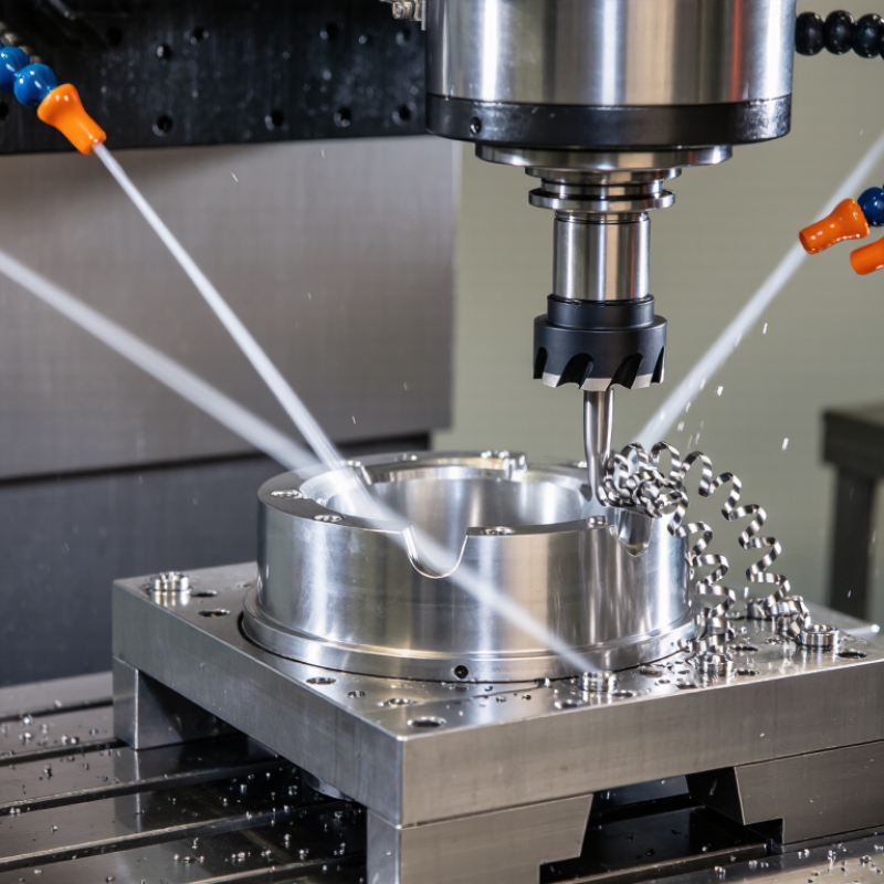
China Top 10 How to Optimize Stainless Milling Feed Rates

Define Stainless Steel Milling Conditions and Feed Rate Variables

Stainless steel milling conditions begin with the alloy, hardness, and work-hardening tendency. Austenitic grades, such as 304 and 316, generate heat quickly and punish rubbing. Confirm the material condition before selecting a feed rate. Annealed stock behaves differently from hardened or cold-worked stock. Tool diameter, flute count, cutter geometry, and edge preparation also affect the starting point.

Feed rate is calculated as Vf = fz × z × n. Here, Vf means table feed, fz means feed per tooth, z means effective flute count, and n means spindle speed. Radial engagement changes the real chip thickness, especially during light side milling. Axial depth, coolant delivery, machine rigidity, and tool overhang must be recorded. A rigid setup can accept more feed. A flexible setup usually needs less.

Chip color matters. A steady cutting sound and short, controlled chips often indicate balanced conditions. I usually begin conservatively, then increase feed in small steps while watching spindle load and surface finish. Do not guess. Excessive feed may chip the edge, while insufficient feed can cause rubbing and rapid work hardening. I have sometimes blamed the cutting tool for poor results when the real problem was weak fixturing. That mistake is easy to repeat. Record each trial, including alloy, cutter engagement, feed per tooth, coolant flow, and measured tool wear.

Select Cutting Tools and Machine Parameters for Stainless Steel

Stainless steel rewards control, not simply higher cutting speed. Its low thermal conductivity pushes heat toward the tool and cutting zone. Heat builds quickly. Excessive rubbing can create work hardening, making the next pass harder. I usually choose a sharp carbide cutter with a positive rake and polished flutes. Uneven tooth spacing can also reduce vibration during slotting or side milling.

Set feed rate from feed per tooth, tooth count, and spindle speed. The basic calculation is feed rate equals chip load multiplied by teeth and revolutions per minute. Begin with a moderate chip load, then increase it only when chips remain short and consistent. A feed that is too low may rub instead of cut. That mistake is common. Keep radial engagement modest for full-depth work, and increase axial depth only when the machine remains rigid.

Use stable workholding and minimize tool stick-out. Flood coolant or a properly directed cutting fluid can remove heat, but it cannot correct poor chip evacuation. Watch the sound, spindle load, and edge condition after each pass. In my shop trials, conservative starting values often produced better tool life than aggressive chart settings. Still, fixed charts are not enough; stainless grades, hardness, and machine power vary widely. I would test one controlled adjustment at a time. Sometimes the best improvement is not a faster feed, but a cleaner setup.

China Top 10: How to Optimize Stainless Milling Feed Rates

Typical starting feed rates for carbide end mills cutting 304/316 stainless steel in side-milling operations. The values assume four flutes, conventional coolant, moderate radial engagement, and stable machine conditions.

Feed rate is calculated from spindle speed, flute count, and feed per tooth. Begin conservatively, then adjust according to tool wear, cutting sound, chip formation, workholding rigidity, radial engagement, and material condition. Reduce the feed rate for deep axial cuts or poor rigidity, and increase it only when chip evacuation and cutting stability remain acceptable.

Calculate the Starting Feed Rate from Cutter and Material Data

China Top 10: How to Optimize Stainless Milling Feed Rates

Calculate the starting feed rate from cutter and material data. For stainless steel, begin with spindle speed, cutter teeth, and feed per tooth. The formula is simple: Vf = n × z × fz. A four-flute cutter running at 2,000 rpm with 0.05 mm per tooth gives 400 mm/min.

ASM Handbook, Volume 16, identifies austenitic stainless steel as thermally resistant, with conductivity near 15 W/m·K. Heat therefore stays near the cutting zone. For a small carbide cutter, a cautious starting range is 0.03–0.08 mm per tooth. Confirm the cutter diameter, radial engagement, and machine rigidity before increasing feed. The U.S. Geological Survey’s 2024 Mineral Commodity Summaries also reports stainless production depends heavily on chromium and nickel, elements associated with tough, work-hardening alloys.

Watch the chip, not only the calculation. A curled silver chip usually indicates useful shearing. Blue chips, edge buildup, or rising spindle load suggest excessive heat or rubbing. Increase feed in 5–10% steps when the cut sounds stable. Reduce it when vibration appears.

The first estimate may be wrong.

Real shops often discover that a theoretical feed rate feels too aggressive after tool wear begins. Coolant delivery, clamping, and interrupted cuts can change the result quickly. Record rpm, feed, engagement, chip appearance, and tool life after each trial. This creates a more reliable starting database for future stainless jobs.

Adjust Feed Rates for Roughing, Finishing, and Complex Features

China Top 10 How to Optimize Stainless Milling Feed Rates

Adjusting feed rates for stainless steel requires control, not guesswork. During roughing, use a moderate feed per tooth and a larger axial engagement. For 304 stainless, practical starting values often range from 0.05 to 0.12 mm per tooth, depending on cutter diameter and rigidity. A 2023 review in the Journal of Materials Processing Technology reported that unstable cutting conditions can sharply increase cutting forces and tool wear. Keep the tool engaged. Avoid rubbing.

Finishing needs a lighter radial engagement, but the feed should not become excessively low. A feed of 0.02 to 0.06 mm per tooth can protect surface quality while maintaining chip formation. The same review linked heat buildup with poor chip evacuation and faster edge failure. For thin walls, reduce radial depth before reducing feed. Complex features require shorter tool stick-out, steady coolant delivery, and smaller stepovers. In practice, I still adjust by sound and chip shape. Calculated values are useful, but stainless steel rarely behaves perfectly.

Tips: Start 10% below the calculated feed, then increase it after checking chip color, burrs, and spindle load. For deep pockets, reduce axial engagement and use a controlled ramp. Industry cutting-data tables commonly recommend lower speeds for austenitic stainless grades than for aluminum, often by more than half. Record each result. A small trial coupon can prevent a costly full-part mistake.

Monitor Results and Optimize Feed Rates for Stable Milling

Stable stainless milling starts with observation, not a calculator alone. I watch spindle load, cutting sound, chip shape, and the finish after each pass. A steady sound usually supports a stable cut, while squealing can signal rubbing or poor engagement. Discolored chips may indicate excessive heat. Record feed per tooth, cutter diameter, radial engagement, axial depth, coolant flow, and material grade. These details make later adjustments traceable and defensible.

When the edge remains sharp and the load is stable, increase feed in small steps, such as five percent. Run a short test path before committing to a full component. Measure burr height and surface roughness at the same locations. If vibration appears, do not reduce feed automatically. Check tool overhang, workholding, runout, and chip evacuation first. A feed rate that is too low can cause rubbing, work hardening, and faster edge wear. Cooling must reach the cutting zone, especially inside deep pockets.

My first setting is rarely perfect. That is normal. Material batches vary, and a polished surface can hide early edge damage. I therefore compare results across several parts, not one attractive sample. If load rises gradually, reduce engagement or feed slightly and inspect the edge under magnification. If the cut stays quiet but chips are thin and dusty, feed may be too conservative. Keep it repeatable. Keep a simple log with the change, observed response, and next trial. Small, measured corrections usually outperform dramatic adjustments made from guesswork.

FAQS

How do you calculate the starting feed rate for stainless steel milling?

Use Vf = n × z × fz. For example, 2,000 rpm, four flutes, and 0.05 mm per tooth produce 400 mm/min. Check machine rigidity before increasing it.

What feed per tooth range suits a small carbide cutter?

A cautious starting range is 0.03–0.08 mm per tooth. Confirm cutter diameter, engagement, and tool overhang. The first estimate may be wrong.

How should roughing and finishing feed rates differ?

Roughing often starts around 0.05–0.12 mm per tooth. Finishing commonly uses 0.02–0.06 mm per tooth. Do not lower feed excessively, or rubbing may occur.

What chip appearance indicates a healthy cut?

A curled silver chip usually suggests useful shearing. Blue chips, edge buildup, or thin dusty chips need attention. Watch the chip.

How should you adjust feed after a stable test cut?

Increase feed in small steps, such as 5–10%. Check spindle load, cutting sound, burrs, and surface finish after each change. Do not make dramatic adjustments.

What should you do when vibration or squealing appears?

Check tool overhang, workholding, runout, engagement, and chip evacuation. Reduce radial or axial engagement if needed. Lowering feed alone may worsen rubbing.

How can thin walls and deep pockets affect feed settings?

Thin walls usually benefit from smaller radial engagement. Deep pockets need shorter tool stick-out and reliable coolant delivery. Controlled ramping can reduce cutting shock.

What information should be recorded during feed-rate trials?

Record rpm, feed per tooth, cutter diameter, engagement, material grade, coolant flow, and tool life. Also note chip color, sound, burr height, and surface roughness. Small logs reveal patterns.

Conclusion

Optimizing stainless steel milling requires a clear understanding of how cutting conditions affect tool life, surface quality, and production stability. This guide explains how to optimize feed rates for stainless steel milling by evaluating material behavior, cutter diameter, tooth count, spindle speed, cutting depth, and machine rigidity. It also shows how to use cutter and material data to calculate a practical starting feed rate instead of relying on guesswork.

The recommended approach is to adjust feed rates according to the operation. Roughing may require a stronger, more productive setting, while finishing calls for controlled motion and consistent surface quality. Complex features, thin walls, and corners often need additional feed reductions to prevent vibration or excessive heat. By monitoring chip formation, cutting sound, tool wear, power demand, and finished dimensions, operators can make gradual adjustments and establish stable, repeatable milling conditions.

Aria

Aria

Aria is a dedicated marketing professional with a deep passion for innovative strategies and a keen understanding of our company's product offerings. With a wealth of experience in the industry, Aria excels at crafting engaging content that highlights the unique features and benefits of our......