Why High Feed Milling Tools Reduce Cycle Time?
Manufacturers increasingly ask how to reduce cycle time with high feed milling tools without sacrificing tool life or surface quality. High feed cutters use small axial depths and aggressive feed rates. Their lead angles direct cutting forces into the spindle, rather than pushing heavily against the workpiece. This allows stable material removal, especially in pockets, cavities, and difficult-to-reach areas. Seco Tools’ High Feed Milling technical guidance reports that this strategy can deliver several times higher feed rates than conventional milling, depending on cutter geometry, material, and machine capability. Sandvik Coromant’s metalcutting guidance also stresses matching cutting data to spindle power, rigidity, and chip evacuation.
Dr. Tony Schmitz, a recognized machining dynamics researcher, states, “The process is a system, and every element must be considered.” That principle matters here. A faster feed rate alone does not guarantee a shorter cycle. Tool engagement, ramping, coolant delivery, and workholding must work together. NIST manufacturing studies repeatedly identify process stability and data-driven parameter selection as major productivity factors. In practice, a stable high-feed pass may remove material while the tool traces a shallow path across a steel pocket. The spindle sounds steady, and chips leave the cavity cleanly. That is the target.
Results can still disappoint. A rigid cutter may overload a weak spindle. Excessive feed may create vibration or poor corners. Therefore, cycle-time reductions should be verified through measured cutting time, tool wear, and part inspection. The most reliable improvement is rarely the most dramatic one.
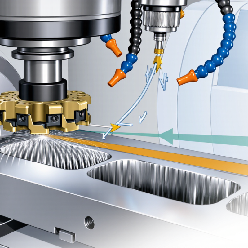
High feed milling tools reduce cycle time by moving quickly across the workpiece. Their cutting geometry uses a very small lead angle. This directs much of the cutting force downward into the spindle and machine table. The result can be a more stable cut, even when material removal rates rise.
The tool usually takes a shallow axial cut and a wider radial pass. Its feed per tooth can be high because chip thinning reduces the actual chip thickness. For example, a cutter may remove material at 1.0 mm axial depth while traveling rapidly across a steel pocket. The chips should appear short and controlled, not long and tangled. Air blast or suitable coolant helps clear them from the cutting zone.
Setup quality still matters more than impressive catalog numbers. A rigid holder, short tool projection, and accurate workholding reduce vibration. I have found that checking spindle load during the first pass reveals problems early. High feed is not magic. Thin walls, weak fixtures, or incorrect chip-load calculations can cause chatter and poor surfaces. The strategy may also leave more finishing stock than expected. That requires a later pass, which can reduce the time saved. Operators should adjust feed, radial engagement, and toolpath direction after observing the actual cut. The safest result comes from measured testing, not speed alone.
Why High Feed Milling Tools Reduce Cycle Time?
The Role of Feed Rate in Cycle Time Reduction
Feed rate directly controls how quickly a milling tool moves through material. High-feed milling tools use shallow cutting depths and larger feed per tooth. This combination removes material efficiently without demanding extreme cutting forces.
A practical example is a pocketing operation in hardened steel. Instead of pushing one deep pass, the tool takes several shallow passes at a higher feed rate. The cutter maintains a stable engagement angle. Chips leave the pocket quickly. Heat also has less time to build at the cutting edge.
Small changes matter. Increasing feed per tooth can shorten cutting time significantly. However, the machine must support the required acceleration and torque. A flexible setup may produce vibration, poor surface finish, or premature tool wear. The workholding, spindle condition, and toolpath all influence the real result.
Feed rate should be adjusted through controlled trials. Start with the tool maker’s recommended range, then watch spindle load and chip shape. Long, glowing chips signal a problem. Powdery chips may show excessive rubbing. In production, the fastest setting is not always the most reliable one. Some operators increase feed too aggressively and lose time through repeated tool changes. That mistake is easy to make.
| Machining Case | Spindle Speed (rpm) |
Number of Teeth |
Feed per Tooth (mm/tooth) |
Feed Rate (mm/min) |
Cutting Path (mm) |
Calculated Cutting Time (sec) |
Cycle-Time Reduction |
Material Removal Rate (cm³/min) |
|---|---|---|---|---|---|---|---|---|
| Conventional Milling – Baseline | 6,000 | 4 | 0.08 | 1,920 | 300 | 9.38 | — | 23.04 |
| High-Feed Milling – Moderate Increase | 6,000 | 4 | 0.16 | 3,840 | 300 | 4.69 | 50.0% | 46.08 |
| High-Feed Milling – Higher Spindle Speed | 8,000 | 4 | 0.16 | 5,120 | 300 | 3.52 | 62.5% | 61.44 |
| High-Feed Milling – Maximum Example | 8,000 | 5 | 0.20 | 8,000 | 300 | 2.25 | 76.0% | 96.00 |
High-feed milling tools shorten cycles through geometry, not brute force. Their low lead angle directs much of the cutting force axially into the spindle. This reduces radial deflection and supports heavier feed rates. A 2022 review in the CIRP Journal of Manufacturing Science and Technology reported feed-rate increases of two to four times in suitable roughing operations. The result is visible at the machine: shorter passes, fewer tool changes, and steadier motion across broad surfaces.
Small lead angles also create thin chips. The cutter can advance quickly without exceeding the programmed chip thickness. Robust inserts, strong edge preparation, and optimized chip breakers protect the cutting edge during interrupted cuts. Differential pitch can reduce harmonics, especially when machining thin walls or uneven stock. Short tool overhang remains essential. Tool design cannot cancel poor setup practice.
The promise is not automatic. I have seen cycle-time gains disappear when feeds were raised without checking spindle load, workholding, or chip evacuation. A 2023 technical report from the International Academy for Production Engineering stresses that cutting performance depends on tool geometry, machine dynamics, and workpiece stability together. Another review in the Journal of Manufacturing Processes links high-feed strategies with improved material removal rates, but also notes higher demands on programming accuracy. In practice, a 30% reduction is plausible, not guaranteed. Test cuts still matter.
Why High Feed Milling Tools Reduce Cycle Time?
How Cutting Conditions Affect Machining Efficiency
High-feed milling tools reduce cycle time through controlled chip removal, not speed alone. Their shallow axial cuts let the cutter travel quickly across the workpiece. Feed per tooth becomes critical. If it is too low, the insert rubs instead of cutting. If it is too high, vibration and edge damage can appear.
A practical setup balances spindle speed, feed rate, axial depth, and radial engagement. For example, a cutter may use a 0.5 mm axial depth with a high table feed. This removes material efficiently while keeping cutting forces directed into the spindle. Short tool overhang also matters. A long extension can turn a productive pass into a noisy, unstable operation. Watch the chips.
In machining trials, operators should adjust one condition at a time. Start with the tool maker’s recommended chip load, then inspect chip shape and surface finish. Increase feed gradually when the sound remains steady and the chips stay compact. Coolant or air should clear chips from the cutting zone, especially in pockets. I have seen cycle time targets fail because the feed rate was raised without checking workholding stiffness. That mistake creates chatter, rework, and sometimes a slower process. Toolpath direction deserves attention too. Smooth entry moves reduce sudden load changes. A small improvement in radial engagement can matter more than a dramatic spindle-speed increase.
The chart uses calculated machining values for a 100 mm toolpath with a four-flute cutter at 6,000 rpm. Feed rate is calculated as spindle speed × number of teeth × feed per tooth. Increasing feed per tooth from 0.05 mm to 0.20 mm reduces theoretical cutting time from 5.00 seconds to 1.25 seconds, while the lower axial depth used by the high-feed condition helps maintain a practical material removal rate.
High feed milling tools reduce cycle time by moving quickly across a workpiece with shallow axial cuts. Their cutting geometry directs force into the spindle, allowing higher feed rates and smoother engagement. A typical roughing pass may remove material efficiently while leaving a predictable surface for finishing. This approach works well for die cavities, aerospace pockets, mold bases, and large open surfaces. It is especially useful when the machine has limited spindle power but strong feed capability.
The method has clear limits. High feed tools are not ideal for deep slotting, sharp internal corners, or thin walls that can vibrate under pressure. In a narrow pocket, chips may collect around the cutter and damage the surface. Coolant direction and air flow matter more than many operators expect. A rigid setup is essential. Even a small workholding error can produce visible marks along the floor. Toolpaths also need smooth transitions, because sudden direction changes increase load. In practical machining trials, reducing axial depth improved stability, but it sometimes required another finishing pass. That trade-off can erase the expected time savings. I have also seen operators increase feed too quickly, then blame the cutter for poor finish and uneven wear. Cutting data should come from the tool geometry, material, machine stiffness, and actual chip evacuation conditions. Fast is useful. Controlled is better.
They remove material quickly across a workpiece. Their shallow cuts and high feed rates can reduce cycle time.
A small lead angle directs much of the cutting force downward. This pushes force toward the spindle and machine table. The cut may feel steadier.
The tool often uses a shallow axial depth and wider radial engagement. For example, it may cut 1.0 millimeters deep across a steel pocket. Feed per tooth can remain high.
Chip thinning reduces the actual chip thickness. This allows higher feed per tooth without creating equally thick chips. The calculation must still match real conditions.
Chips should be short and controlled. Long, tangled, or glowing chips suggest trouble. Powdery chips may indicate rubbing.
Use a rigid holder, short tool projection, and accurate workholding. These details reduce vibration during rapid passes. A weak fixture can ruin an otherwise good strategy.
Begin within the recommended cutting range. Watch spindle load, chip shape, sound, and surface finish. Adjust feed, radial engagement, or toolpath direction gradually. Measured testing works better than speed alone.
No. Thin walls, poor fixtures, or limited machine acceleration can create chatter. Extra finishing stock may also require another pass. The fastest setting is not always the fastest process.
Air blast or suitable coolant can remove chips from the cutting zone. Clear chips prevent recutting and heat buildup. The correct choice depends on the material and operation.
High feed milling tools are designed to remove material efficiently by combining shallow cutting depths with exceptionally high feed rates. Instead of relying on deep radial engagement, their geometry directs cutting forces more axially into the machine and workpiece, helping maintain stability while increasing material removal. This approach explains how to reduce cycle time with high feed milling tools: the tool travels faster across the workpiece, completes passes more quickly, and can reduce the number of machining operations required.
Their performance depends on features such as a small lead angle, rigid cutting edges, optimized flute geometry, and effective chip evacuation. However, faster milling is only beneficial when feed rate, spindle speed, depth of cut, coolant, and workpiece material are properly balanced. High feed tools are especially useful for roughing large cavities, molds, and complex components, but they may be less suitable for deep slotting, thin walls, sharp internal corners, or operations requiring a superior surface finish. Careful setup and appropriate cutting conditions are essential for achieving reliable cycle-time reductions.

DentFix Tool